|
 |
This install takes 45 minutes to an hour. This install will work for cars with or without navigation. As a side note, 2001 and early 2002 cars had a different left side trunk liner if a factory changer and/or navigation were not installed by the dealer. The pre-wire is there in all cars but the side panel in the noted cars does not have the bulge and door for the changer/nav unit and there is no factory bracket. If your car fits the preceding description, you can either mount the changer under the rear deck or get the new side panel and bracket from your dealer.
Click on the images for larger views. |
NOTE:
- You may want to disconnect the battery to avoid doing damage to your electrical system while performing this install. Since I skipped that step, I did not include a section on the subject in this DIY. It is generally considered good practice to disconnect power anytime you work on the electronics in your car. I feel better having said that.
|
Step 1: Getting the required items together
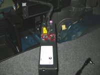
This install requires:
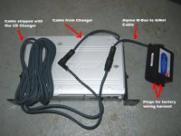
- Alpine CHA-S634 6 Disk CD/MP3 Changer
- Alpine M-Bus to AiNet Adaptor (KCA-130B)
- Soundgate BMW to Alpine Changer Interface (ABMW35V5)
- Factory Changer Brackets
- Small Flat Screwdriver
- Philip screwdriver
- 8mm Socket and Ratchet or Driver
- Double Sided Tape
- Zip Tie
- BMW E46 M3
- 45 minutes to an hour of free time.
|
 |
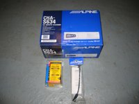
The Stuff You Need |
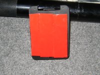
Step 2: Removing the tail light assembly
- You will need to remove the carpeted section on the driver's side of the vehicle's trunk liner to get to the CD changer - You need to remove the tail light assembly in order to do this.
- From inside the trunk, locate the light assembly at the rear of the trunk (directly behind the exterior lens).
- Note the interior light located at the back of the assembly.
- At the fender side of the interior light note the location of the release tab (see image).
- Push the tab toward the center of the car - you will feel the assembly come free.
|
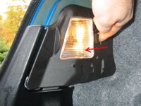
Releasing the Tab
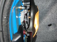
Releasing the Assembly |
Step 3: Unplug the light assembly
- Pull the assembly straight back to remove it out of the lens.
- At the bottom of the assembly there is a plug which you should disconnect to make your life easier for the rest of the instal by getting the light assembly out of your way - see image.
|
Plug Location |
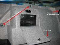
Step 4: Removing the carpeted drivers side trunk liner
- The liner is held in place by 2 plastic retainers, one metal hoop (tie down hook) and a plastic cover under the back of the rear seat (see image).
- To remove the plastic retainers first use a small screwdriver to carefully pop out the center of the retainer (see images).
- Once the center part of the retainer is all the way out, use the screwdriver to pop out the larger base section (see images).
- Lower the driver's side rear seat.
- Starting at the tail light, carefully pull the carpeted cover out of the vehicle. Be especially careful when pulling the last part out that is located toward the top of the rear seat back. The carpeted sections is covered by a plastic piece - be gentle, don't brake the plastic piece.
|
Retainer Locations
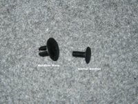
Removed Plastic Retainer
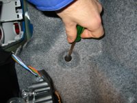
Removing the Center Pin |
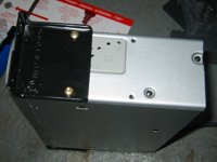
Step 5: Removing the stock changer
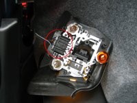
- Once the lining is out, take a moment to examine the factory bracket and changer installation.
- Note that the changer and the tray under it are independently mounted with 4 8mm bolts each (see image).
- Remove the tray first and set it aside.
- Remove the changer next. Once unbolted, gently work it out of the bracket - be careful not to damage the wiring harness that is attached to the back of the changer.
- Once you have it out, unplug the two connectors at the rear of the changer (see image).
|
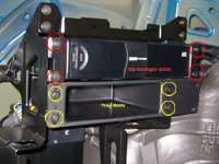
Bolt Locations
Wiring Harness Locations |
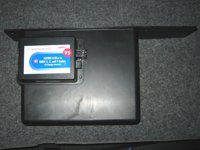
Step 5A: Where No Stock Changer Is Present
- If you do not have an OE changer or Nav you will have a pair of empty plastic trays behind the panel.
- If you have navigation but no changer you will have the nav unit below and an empty plastic tray on top.
- Note that the tray(s) are independently mounted with 4 8mm bolts each (see image).
- Remove the tray(s) and set it aside.
- If you do not have navigation or a changer hooked up you will have two sets of bundled up cables wrapped up in a fabric like cover.
- Its pretty easy to tell which "bundle" you need for the changer. The changer bundle will have a single cable going into it. The other bundle is for navigation and it has 3 cables going into it.
- Unwrap the bundle with a single cable going in and you will find 2 plugs at the end of the cable - these are the plugs that will go into the Soundgate interface.
|
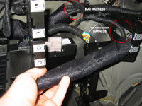
Cable Bundles
Changer Plugs |
Step 6: Removing the factory mounting brackets
- The stock changer has brackets mounted on both sides.
- You will need to remove these and reuse them when installing the Alpine changer.
- Each bracket is held in place by 2 Phillips screws (see image).
- You're done with the stock changer at this point so set it out of the way.
|
Removing the Brackets |
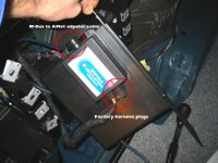
Step 7: Understanding what needs to plug into where
- Take a second to understand what you will be plugging into what to get things to work. This is a dry run - you will be taking this back apart to install. Refer to the image for details.
- The M-Bus to AiNet adaptor cable plugs into the circular plug on the end of the Soundgate interface with 2 plastic tabs. Use the 90 degree male end.
- The other end (straight) of the M-Bus to AiNet adaptor cable plugs into the long cable that comes with changer.
- The long cable is then plugged into the short cable that is attached to the changer.
- Note the other end of the Soundgate interface. There are two connectors here which match up with the stock CD-changer wiring harness.
|
What Goes Where |
Step 8: Preparing the changer for installation
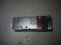
- First, remove the 3 shipping "keys" at the bottom of the changer (see image).
- Remove the plastic tape from the changer door.
- Set the output type selector to M-Bus (see image) by moving the slide switch to position 2 (all the way to the right). Make sure to do this as the factory setting will not work!
- Make sure the changer's orientation is set for horizontal installation (see image). The little metal pin should be in its top most position (this needs to be the same on both sides). If the pins are not in the correct position, pop the plastic covers off on each side and re-orient the pins. Factory setting should be for horizontal installation, but check anyway!
|
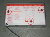
Shipping "Keys"
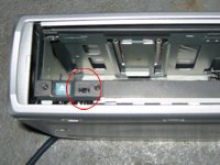
Bus Switch
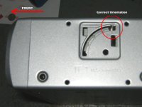
Orientation Pin
shown with plastic cover removed |
Step 9: Installing the mounting brackets
- You will need to reuse the brackets you removed from the stock changer in step 6 above. The brackets that are packaged with the changer will not align with the bolt holes in the factory mount.
- You can either reuse the factory bolts or use the ones packaged with the changer.
- Brackets are interchangeable left to right.
|
Bracket Installation |
Step 10: Mounting the Soundgate interface
- There are probably a hundred ways to do this - the steps below were simply my best guess.
- Cover the underside of the Soundgate interface with double sided tape (see image).
- Attach the Soundgate interface to the bottom left of the stock tray (see image). Make sure that the side with the two tabs and single plug are to the outside. Make sure that the interface edge and not the dual tabs roughly lines up with the edge of the tray. The tabs should stick out a bit over the edge of the tray - you have to do it this way in order to be able to plug the cable into the side of the interface. Mount the interface about an inch back from the front of the tray.
|
Taped Up Bottom of Interface
Location and Orientation of Interface |
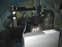
Step 11: Wiring things up
- Plug the M-Bus to AiNet adaptor cable into the long cable that was packaged with the changer (see step 7 above).
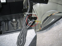
- Bundle the cable up leaving about a foot of free cable at each end and use you zip tie to keep it together.
- Place the bundled cable into the "triangular" recess in the fender well behind where the tray will mount (see image - unfortunately the image shows the tray already in place).
- Make sure that the Soundgate interface is tightly attached to the bottom of the tray and connect it to both the M-Bus to AiNet adaptor cable and to both of the factory plugs (see image).
- You may have to work the factory harness into a good location to get at it.
|
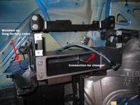
Hiding the Long Cable
Connecting the Interface |
Step 12: Reinstalling the tray
- Inspect the 8 silver clips to which the changer and tray will mount - realign them as necessary.
- Slide the tray back into place making sure that the changer lead is on top of the tray (see top image for step 10).
- Replace the 4 screws but do not tighten the tray down yet.
|
|
Step 13: Installing the new changer
- Plug the cable end you left on top of the tray to the cable from the changer (see image).
- Slide the changer into place.
- Replace the 4 mounting screws.
- This is as good a time as any to test to make sure everything works - slap a disk in the changer and if you did everything correctly you should be treated to music.
- If the changer does not respond, check all of the wiring for loose connections.
- If all is well, tighten down the 4 bolts holding the changer.
- Push the tray up a little bit so that its flush with the changer and snug up the 4 bolts that hold it in place.
|
Connecting the Changer
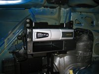
New Changer in Place |
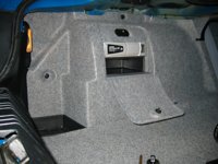
Step 14: Reinstalling the carpeted liner
- Start at the tail light lens area and slide the edge of the liner in the grove in the back of the trunk.
- Work you way forward pushing the liner in place (groves along the bottom of the trunk).
- Slide the forward edge of the liner back under the plastic cover at the top of the rear seat back.
- Force the liner down around the metal hoop on the floor of the trunk.
- Insert the plastic retainer bases into the holes in the liner (see image from step 4 for locations).
- Push the center piece back into the retainer bases.
|
|
Step 15: Reinstalling the tail light assembly
- Reconnect the wiring harness to the tail light assembly.
- Line the bulbs up with the holes in the lens assembly.
- Push the assembly in until it clicks
- You're done! Enjoy the music!
|
All Done! |

|